Four-anemometer system
Our standard ceiling fan system, described on this page. Four anemometers on individual servo linear actuators measure all four radii at once, with automatic diaphragm changeover and pneumatic fan lift included.
Runs the complete IS 374 air delivery test at the push of one button. Four anemometers move to every measuring position on their own, every reading is logged, and the report is written and filed automatically. Also built as a lower-cost single-anemometer system, and for TPW fans to IS 555. Four systems are in use at ceiling fan manufacturers.
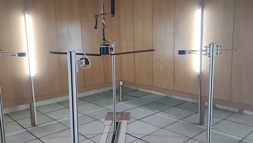
A manual air delivery test means moving anemometers by hand, reading meters and writing up the results, and every step depends on the person doing it. This system automates the whole test: it lifts and aligns the fan, sets the right diaphragm for the sweep, moves the anemometers through every position, records each reading and produces the report.
A programmable test sequence runs the full IS 374 air delivery test and generates the report the moment it ends.
SCADA shows the test status and live readings away from the test site, and lets you control the setup remotely.
A multi-stage pneumatic lift raises and lowers the fan, designed to keep the space above the fan clear for airflow. The diaphragm changes automatically for each sweep.
Run several tests back to back with no operator, to check how consistently a fan performs.
The operator enters the fan details and presses start. Everything after that is automatic.
Enter the fan model and sweep. The system sets the matching diaphragm by itself.
The pneumatic lift positions the fan, and a laser or plumb line aligns the fan centre with the anemometer centre.
Four servo-driven anemometers traverse 17 positions along each axis, with every reading logged and time-stamped.
The report is generated in your format, named with the model, sweep and test end time, and filed by date and month.
Taken from a system in use at a ceiling fan manufacturer.
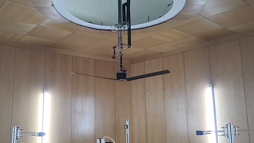
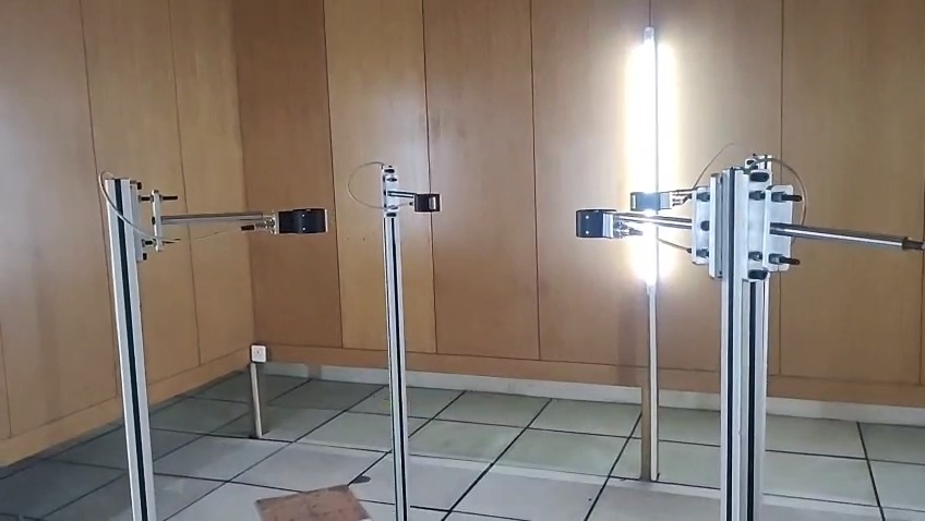
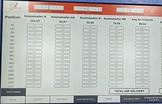
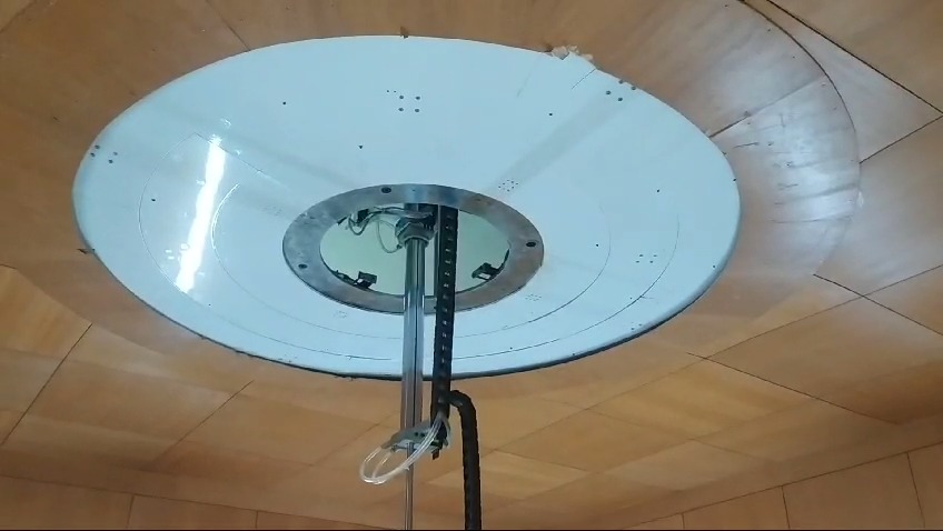
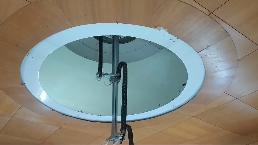
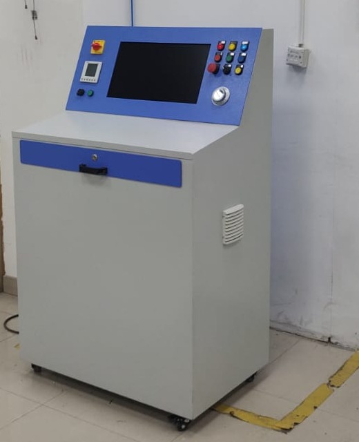
All three run a programmable, one-button test under SCADA, log every reading against its position and generate the report automatically.
Our standard ceiling fan system, described on this page. Four anemometers on individual servo linear actuators measure all four radii at once, with automatic diaphragm changeover and pneumatic fan lift included.
The lower-cost option for ceiling fans up to 1400 mm sweep. One anemometer travels along a servo linear axis, and a servo rotary axis turns it to 0°, 90°, 180° and 270° to cover all 68 IS 374 positions. Because the radii are measured one after another, each test takes about four times as long. Fan lift, diaphragm changeover and a measurement and alignment package (voltage stabiliser, temperature and humidity probe, laser alignment) can be added.
For table, pedestal and wall fans, testing air delivery to IS 555. Four anemometers on ball-screw axes, laser alignment, temperature and humidity measurement, electrical readings including power factor, automatic voltage regulation from 180 V to 280 V and regulator testing, with one PLC dedicated to anemometer data.
| Feature | Four-anemometer | Single-anemometer | TPW fans |
|---|---|---|---|
| Fans tested | Ceiling fans | Ceiling fans up to 1400 mm sweep | Table, pedestal and wall fans |
| Standard | IS 374 | IS 374 measuring positions | IS 555 |
| Anemometers | 4, on servo linear actuators | 1, on a servo linear axis with a servo rotary axis | 4, on ball-screw axes |
| Radii | Measured at the same time | Measured one after another; about 4× longer per test | As set by IS 555 |
| Automatic diaphragm changeover | Included | Optional | — |
| Pneumatic fan lift | Included | Optional | — |
| Voltage stabiliser, temperature and humidity, laser alignment | Included | Optional package | Included |
| Separate PLC for anemometer data | Yes | — | Yes |
Four BIS-approved 80 mm vane anemometers on individual servo linear actuators, with sensors confirming each position.
An energy meter records wattage, voltage, current and frequency in real time.
Fan RPM measured automatically and recorded for each position.
Measured throughout the test, because both have a proven effect on air delivery.
Regulated automatically from 180 V to 280 V to match the test input, including low-voltage tests at 180 V.
Test the fan at different regulator settings to see how it performs the way customers actually use it.
One PLC is dedicated to anemometer data acquisition and a second runs the process, so no data is lost to noise or interference.
Every parameter is logged position by position, including live RPM and wattage, giving the detail needed for deeper analysis.
Calibration factors are entered into the system and applied automatically whenever calibration data is updated.
The diaphragm for each sweep is set from the fan data, with no manual step.
Proprietary analytics show how each fan performs and where its performance can be improved.
A live, navigable video of the test chamber on any screen, so the test can be watched without entering the chamber. Useful for showing the process to management and visitors.
A lock on the test chamber controlled through SCADA, so no one can enter without logging in and nothing can disturb a test while the operator is away.
Thermal imaging of the fan shows how its temperature changes during the test and how that affects performance.
Acoustic testing of the fan, with analysis of the airflow's acoustic profile to understand disturbances to laminar flow.
Values for the four-anemometer ceiling fan system. Final values are confirmed in the techno-commercial offer for your test room and fan range.
| Parameter | Unit | Value |
|---|---|---|
| Test standard | — | IS 374 |
| Anemometers | — | 4, BIS-approved 80 mm vane type |
| Measuring positions | — | 17 along each axis |
| Anemometer drive | mm | Individual servo linear actuators, 1450 travel, on precision guide rails |
| Control | — | Two PLCs (anemometer data, process) with SCADA |
| Measured | — | Air velocity, RPM, wattage, voltage, current, frequency, temperature, humidity |
| Test voltage | V | 180 to 280, regulated automatically |
| Fan handling | — | Multi-stage pneumatic lift |
| Diaphragm | — | Automatic changeover by fan sweep |
| Alignment | — | Laser, or plumb line |
| Reports | — | Automatic; named by model, sweep and test end time; filed by date |
Anemometers with servo linear actuators, guide rails and position sensors; PLC control panel; SCADA; multi-stage pneumatic fan lift; automatic diaphragm changeover system; energy meter; temperature and humidity probe; automatic voltage stabiliser; laser alignment; computer and printer for records and reports. Installed and commissioned at your plant, with operator training.
Automatic diaphragm changeover needs either 5.5 m clear height from floor to ceiling, or 1.5 m of clear space above the ceiling for the mechanism.